技術開発
[Earth-Conscious][Composite Technology][The Making of Carbon Monocoque]Earth-Conscious
TUT FORMULAでは設計,企画段階において環境負荷を可能な限り低減させることを目指しています.|
DfX =Design for X |
DfD=Design for Durabillity(耐久性を配慮した設計) DfS=Design for Safety(安全性を配慮した設計) DfS=Design for Size(サイズを配慮した設計) DfD=Design for Diassembly(分解容易性を配慮した設計) DfE=Design for Environment(環境を配慮した設計) DfR=Design for Recycling(リサイクルを配慮した設計) |
DfX(Design for X)と総称される概念をベースに,"X"として製品競争力を高めるための製品設計・開発手法に関するキーワードを充てることが知られていますが,今回はDfR DfEに関しての取り組みを紹介します.
DfR DfE
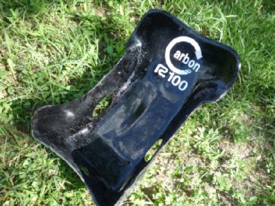
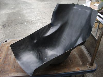
エポキシ複合材料として最も注目されているエポキシ系CFRPの各種リサイクル技術のなかで,LCAへの寄与が期待できる常圧溶解法によるCFRPリサイクル技術に関して,日立化成工業株式会社の協力の元,取り組んでいます.08年度においては,CFRP製の廃棄テニスラケットから取り出したリサイクル炭素繊維を用い作製した不織布を用い,世界初となるリサイクル炭素繊維を100%用いたCFRP製ドライバーシートを製作しました.このことなどが評価され,第6回全日本学生フォーミュラ大会にて「国土交通大臣賞」(安全技術,環境技術,新技術の総合優勝に与えられる賞)などを受賞しました.
一般的には「CFRPはリサイクルが出来ない」と言われており,そのことが自動車へCFRPを適応する際の足枷となっていますが,それに対する1つの解を示せれば,という思いで研究しています.
Composite Technology
TUT FORMULAの 先端複合材料技術(Advanced Composite Materials and Technologies:ACM)は高い評価を頂いています.TG02の段階から,オートクレーブ成型を用いカウルの成型を行ってきました.プリプレグ成型だけではなく,成型に必要な型をドライクロスを用いたCF-Compositeにより製作をするなどチーム設立当初からACMに取り組んでいます.
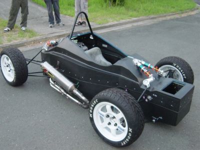
TG03では日本初となるカーボンモノコックを採用.材料選定に始まり,材料試験,そして設計から製作まで全てを学生の手で行いました.その技術,挑戦が認められ,国土交通大臣賞,ユニークデザイン特別賞,New Thinking賞などを受賞することができました.
Design Engineering
設計においては,ACMによるモノコック構造の利点を最大限に生かすことを常に考えています.モノコックはスペースフレームと比較をして,剛性の向上,軽量化,エネルギー吸収量の増加等が期待できます.複雑形状であっても,新しいアイデアを創造し,あらゆる技術を駆使して成立させるコンポジットデザイン・エンジニアリングでは他チームには負けません.
Structure Design CAE & Testing
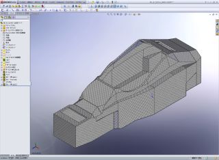
CADの中で Solid/Surface のデジタルモデルを作り込み,構造解析を繰り返し最適構造を作り上げます.ACMを構成する材料には数え切れないほどの種類が存在します.その中から最適な材料を探し出すには幅広い知識が必要です.日々進歩をする業界にアンテナを張り巡らし,絶えず情報収集を行っています.最終的には,材料を部内で成形し,テストピース作成,要素試験,評価などを行うことにより,材料の選定を行っています.また,構造解析で用いる複合材のプロパティはメーカから提示されたものを用いるのではなく,部内で成型し,テストピースを作成し材料試験を行うことによって得られたものを用いています.
Tooling
ACMでは製品設計のみではなくToolingの設計も重要となります.複雑形状ともなると,型の分割を考慮しなければなりません.2分割以上の割型になることもしばしばあります.現在,ToolingにはCF-Compositeを主に用いていますが,用途に合わせてパールボードや金型等による成型も行っています.TUT-FORMULAにおける成型プロセスは,最も高性能なオートクレーブ成型をはじめ,改VARTAM,OVEN VACUUM BAGなどがあり,それぞれの成型に適したものを用いています. 複合材ならではの設計・部品寸法・複雑形状の自由度を実現します.
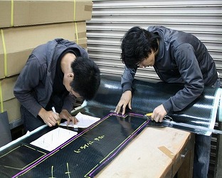
Laminate
活動場所内に,CFの積層作業や型の製作を行うためのMolding&Laminating roomを設置.換気用ブロアや冷暖房設備を備えています.ACMで問題となる異物の混入が無いように最大限の注意をしています.もちろんモノコックをはじめ,すべての製品は学生のみで積層を行っています.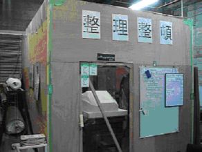
Process
TUT FORMULAでは,これら上記一連の流れの全てを学生の手で行っています.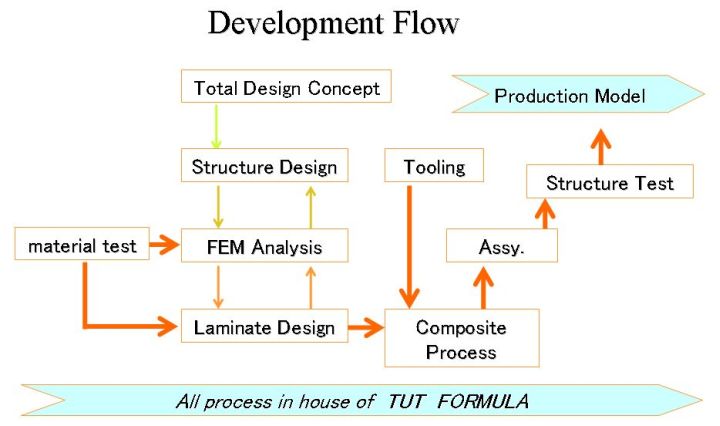
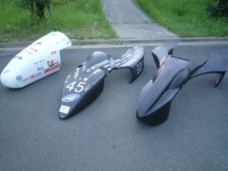
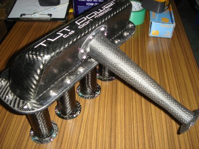
Product
これまでに製作をした製品の一部を紹介します.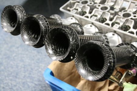
The Making of Carbon Monocoque
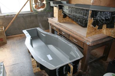
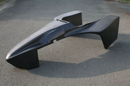
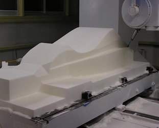
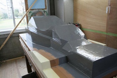
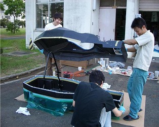
As you know,the process of building a carbon fibre monocoque is quite long and requires excellent preparation. It takes us probably around 3-4 months to complete the entire process with the techniques we use.Firstly, you will need to start with what is known as a plug. Basically, this is CNC machined from foam(sometimes another material) and is an exact representation of what the final chassis will look like. I have put a photo of the bottom half of our plug from last year below.
From this plug, a mould is then constructed. This is done using a high temperature fibreglass and resin, which produces an exact replica of the plug above. It is very important that the surface is perfect and no fibreglass is exposed, otherwise the carbon fibre will stick to the surface when you complete the final carbon fibre chassis.
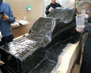
The surface then needs to be treated with either a wax or frekote so that the carbon fibre won't stick when the chassis needs to be removed from the mould above.
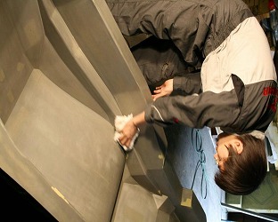
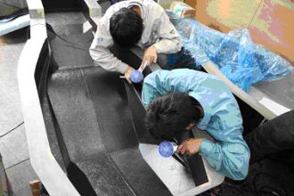
You are now ready to lay-up the carbon fibre. You start by laying an outer skin of carbon fibre into the moulds above. This basically forms the outside surface of the chassis once it is completed. Most teams runs between 2 and 5 layers of carbon fibre in the outer skin.
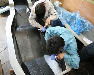
Honeycomb is then placed over the top of the outer skin. This is normally 15mm or 18mm depending on individual teams.Holes must be cut into this for the hardpoints such as suspension, engine mounts (basically anything that needs to bolt into the chassis). Some teams use Bakelite inserts, and some a 6000 or 7000 series aluminium depending on where the insert is positioned, and whether it needs a thread to be cut into it (such as for engine mounts).
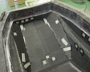
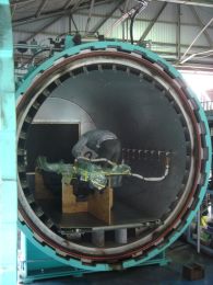
An inner skin is now placed on top of the honeycomb to form the inside of the chassis. This is again typically 2-5 layers of carbon fibre. Once this has been completed, the chassis needs to be vacuum bagged and placed in the autoclave to be curried.
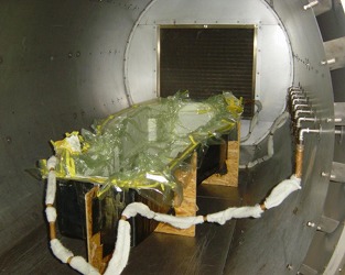
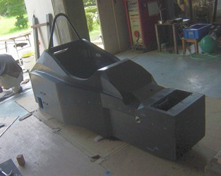
Once this is done, the carbon fibre chassis can be removed from the fibreglass moulds above, and you have your chassis.
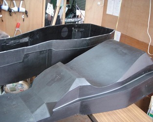
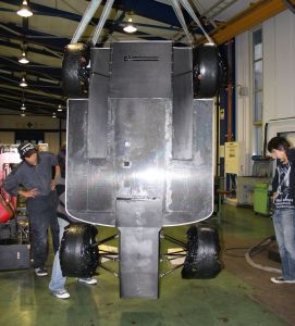
As you can see above, we do our chassis in two pieces (a top and a bottom half:TG03), but some teams do it in a single piece (but its harder and takes much more time:TG04). we just bond the top and bottom halves together to form the chassis.
I hope this helps you out anyway……
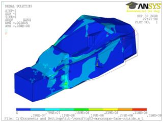
For analysis, we use a program by the name of ANSYS and MECHNICA(look it up on google). It is quite complex to use, but fine once you have had some experience with it. You can also do all of you other FEA (finite element analysis) testing in this program- we use it for everything.

Structural equivalency is a little MORE complex. Basically, everything in the FSAE Rules book which the car must comply with is written for a spaceframe style chassis (like what you are running at the moment). Thus, any rules in which your chassis does not follow from the book, you need to prove that what you have done is just as strong as what is written in the rules book.
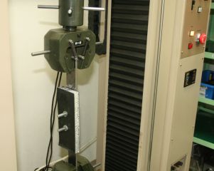
Structural Equivalency for a carbon fibre monocoque usually involves setting up a test rig and doing an impact test (say a small portion of the side of the chassis where the drive sits with the roll hoop mounted in). Usually, this is compared to a spaceframe design, and the results need to show that the carbon fibre monocoque can absorb just as much energy (which is pretty easy as it does lots more than the spaceframe). There are also other tests which need to be completed, such as fibre pullout strength- usually a rig is setup to also test these sorts of things.
Anyway, I hope that this information is helpful, and good luck in the future with the carbon fibre monocoque.
Finally, Here is some additional information which I think you might find useful.
References
1) Braydon, T.H., Darrow, D.C.. 1996, 'A Systems Approach for Improvement of the Manufacturing Process for Composite Honeycomb Sandwich Panels', Proceedings of the 28th International SAMPE Technical Conference, pp 1300-1308.
2) Ji, K.J., Wei, C.Y., Deng, W.H., Zhang, Y.S., Liu, Y.J., Mao, R.Z. and Wang, X., 2002,Evaluation of Glass Fibre/ Epoxy Prepreg Quality During Storage, Polymers and Polymer Composites, vol. 10, no. 8, pp 599-606.
3) Abot J.L., Daniel I.M., 2001, 'Composite Sandwich Beams Under Low-Velocity Impact',American Institute of Aeronautics and Astronautics.
4) Allen, H.G., 1969, 'Analysis and Design of Sandwich Panels', Permagon. Hajime, K., Akira, N., Nobuyuki, O., 2001 'self-adhesive type honeycomb co-cure prepreg'SAMPE Journal, vol. 37, no. 2, pp. 89-92.
5) Thompson, R.W., Matthews, F.L., O'Rourke, B.P., 1995, 'Load Attachment for Honeycomb Panels in Racing Cars', Materials and Design, vol. 16, no. 3, pp. 131-150.
6) Campbell, F.L., Mallow, A.R., Browning, C.E., 1995, ??Porosity in Carbon Fibre?? Composites An Overview of Causes, Journal of Advanced Materials, vol. 26, no. 4, pp. 18-33.
7) Hayes, B. S., Seferis, J. C., Edwards, R. R., 1998, 'Self-adhesive honeycomb prepreg systems for secondary structural applications' Polymer Composites, vol. 19, no. 1, pp 55-64.
8) Burchardt, C., 1998, 'Fatigue of Sandwich Structures with Inserts', Composite Structures, vol.40, no. 3, pp. 201-211.
9) Thomsen, O.T., 1998, 'Sandwich Plates with Through the Thickness and Fully Potted Inserts:Evaluation of Differences in Structural Performance' Composite Structures, vol.42 40, no. 2, pp159-174.
10) Way-Nan Yeh, Ye-Ee Wu, 1991, 'Enhancement of Buckling Characteristics for Sandwich Structure with Fibre Reinforced Composite Skins and Core made of Aluminium Honeycomb and Polyurethane Foam', Theoretical and Applied Fracture Mechanics, Vol15, pp 63-74.
11) Shigley, J.E.& Mitchell, L.D., 'Mechanical Engineering Design', McGraw-Hill, latest metric ed.
12) Society of Automotive Engineers, 2008 Formulae SAE Rules.
13) Thomsen, O.T., Rits, W., 1998, 'Analysis and Design of Sandwich Plates with Inserts - A High-Order Sandwich Plate Theory Approach', Composites Part B, vol. 29, pp795-807.
14) Matweb, [Online], www.matweb.com
15) JIS,[Online]http://www.jisc.go.jp/
By yuya,KUSANO